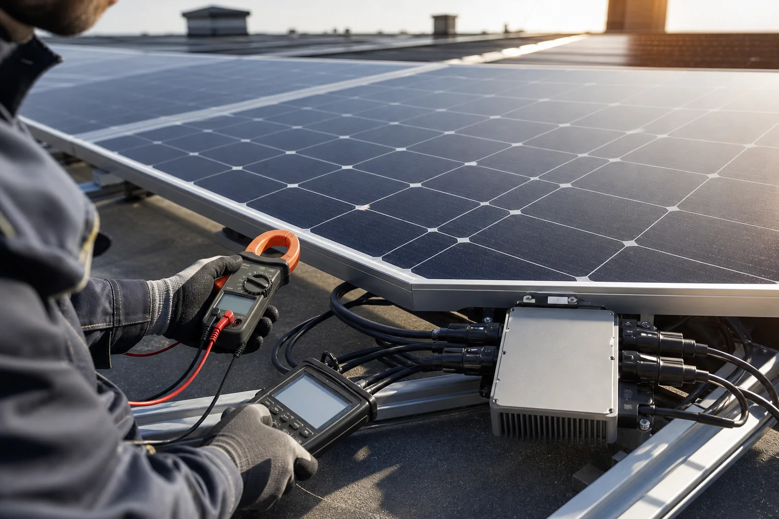
High-Voltage Microinverter Matching for Thin-Film and Perovskite Modules
A supplier-to-supplier data exchange for voltage, current, grounding, connectors and qualification when the module is not conventional crystalline silicon.

TMG Technical Team
Applications Engineering

Thin-film and emerging perovskite module formats can use electrical characteristics that differ from mainstream crystalline-silicon panels. A high-voltage, lower-current inverter architecture may be relevant, but technology labels never replace an exact datasheet and manufacturer-approved interface.
The APHV Series is designed for compatible high-voltage crystalline, perovskite and thin-film modules within its stated 80–230 V working architecture. “Compatible” remains a model-and-module engineering decision.
Request more than the front-page datasheet
Obtain maximum-power and open-circuit voltage, operating and short-circuit current, temperature coefficients, power tolerance, maximum system voltage, grounding restrictions, insulation behavior, connector specification and any inverter requirements stated by the module manufacturer.
For pre-commercial or custom modules, also request the revision-controlled electrical specification, qualification status, expected production tolerances and change-notification process. A laboratory sample must not silently stand in for a future production module.
Calculate the full voltage envelope
Cold conditions can increase Voc; hot operating conditions reduce voltage. Calculate the module or permitted series allocation at both ends and check startup, MPPT window and absolute input maximum. Keep sufficient margin for tolerances and the design method required by the project authority.
Current must be checked per independent input, including Isc and any irradiance or technology-specific behavior provided by the module supplier. Use the general compatibility checklist; for mainstream high-current modules, the separate n-type guide addresses the opposite current-heavy problem.
Review system interactions
| Interface | Question for the two suppliers |
|---|---|
| Grounding | Is either conductor permitted or required to be grounded? |
| Leakage/insulation | Are monitoring and trip behavior compatible? |
| Connectors | Is the exact mating pair approved? |
| MPPT | Does the algorithm support the module's operating behavior? |
| Startup | Is available voltage sufficient under weak irradiance? |
| Safety | What combination-level evaluation is required? |
IEC 62109-3 addresses safety requirements for electronic devices mechanically or electrically incorporated with PV elements. Whether it applies to a proposed commercial combination must be determined by the compliance professionals responsible for that product.
Use a staged validation plan
Begin with calculation and document review, then supplier bench validation, a controlled pilot installation and monitored field observation appropriate to the product maturity. Define pass/fail criteria before testing: startup behavior, stable tracking, insulation alarms, energy capture and fault response.
Send the complete module specification, sample status, wiring proposal, site temperatures and target market through TMG Contact. TMG can screen the electrical fit and identify the evidence or joint validation still required; it should not be treated as approval from the module supplier or local authority.
Sources & further reading
- https://iea-pvps.org/trends_reports/trends-in-pv-applications-2024/
- https://webstore.iec.ch/en/publication/27684
Last reviewed August 21, 2025.