Rooftop Microinverter AC Surge Protection: An SPD Coordination Checklist for EPC Buyers
Specify protection for long rooftop AC branches, compare SPD ratings with exact-model surge evidence, and define installation and maintenance responsibilities before ordering.

TMG Technical Team
Applications Engineering

A rooftop microinverter RFQ should include an AC surge protection review whenever the project team evaluates exposed branch wiring and the building's protection system. A surge protective device (SPD) in the main distribution board does not, by itself, establish the protection available at every rooftop inverter. Cable routes, earthing, the external lightning protection system and device coordination all affect the design.
For EPC buyers and distributors, the useful deliverable is a marked single-line diagram plus an evidence matrix: which circuit is protected, by which SPD, under which installation conditions, and who approves the combination. This article provides the procurement questions; the qualified electrical designer applies the destination market's rules to the actual site.
Start with the AC route and the real product architecture
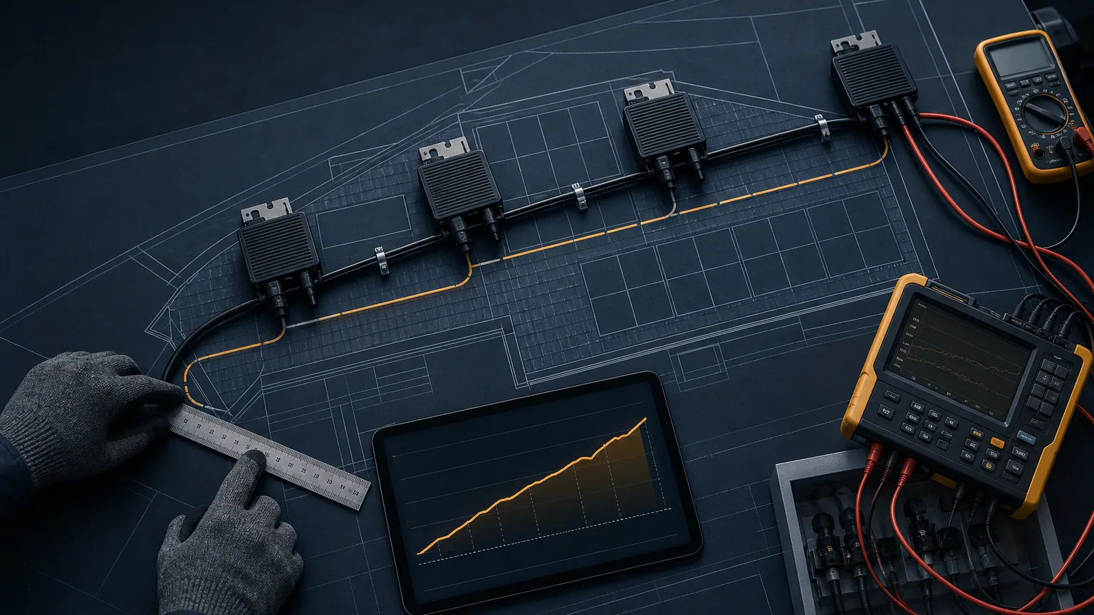
In a conventional module-mounted microinverter system, DC leads can be short while the AC collection circuit crosses a large roof. DEHN's microinverter discussion identifies this difference from string-inverter layouts. Its older white paper illustrates the principle; use current local requirements and current manufacturer application data for the final design.
Do not turn that observation into a blanket decision to omit DC protection. Extended PV leads, different module arrangements, exposed battery wiring and lightning-current paths need their own review. TMG's APLV Series includes hybrid and battery functions; the APHV Series uses a different PV input architecture. A rooftop protection package must match the exact model and connections rather than just the word “microinverter.”
Prepare the branch layout alongside the AC branch-circuit sizing checklist. Overcurrent protection, conductor sizing and transient protection answer different questions and need separate evidence.
Collect six site facts before selecting an SPD
| Site fact | Evidence to collect | Design decision it supports |
|---|---|---|
| AC supply | Voltage, frequency, phases and earthing arrangement | SPD circuit configuration and continuous-voltage rating |
| Lightning protection | Risk assessment, external system, bonding and separation details | Whether lightning current may enter the protected circuit |
| Cable route | Actual board-to-roof and rooftop branch lengths | Protection locations and coordination distances |
| Equipment boundary | Inverter, junction box, gateway, battery and backup circuits | Which ports and circuits need review |
| Fault environment | Prospective short-circuit current and upstream devices | SPD short-circuit capability and backup protection |
| Service access | Cabinet location, indication and replacement access | Inspection and maintenance plan |
Measure cable length along its installed route, including risers and branch runs. Keep the existing SPD's exact part number and datasheet; a photograph of a green status window alone does not establish its ratings or coordination with a second device.
Decide Type 1 and Type 2 from the exposure assessment
Type 1 devices address lightning-current duty; Type 2 devices address surge duty such as induced and switching transients. Combined devices can cover both duties where specified. Selection depends on the site's lightning-current paths and installation rules. The presence of an external lightning protection system, maintained separation distances and bonding arrangement should be reviewed together.
IEC 61643-32 covers selection, installation and coordination principles for PV-system SPDs, including the AC side. IEC 61643-12 provides selection and coordination principles for AC circuits. Ask the designer to identify the editions and national implementation used, then obtain the SPD manufacturer's coordination instructions for the chosen devices.
“Type 2 at every inverter” is not a complete specification. Neither is assuming one Type 1 device at the service entrance solves the entire roof. Draw the protective zones, circuits and locations first, then select compatible devices and installation details.
Compare ratings that describe different duties
| SPD parameter | What the buyer needs to confirm |
|---|---|
| Uc: maximum continuous operating voltage | Suitable for actual supply voltage and earthing configuration |
| Up: voltage protection level | Compatible with protected equipment, allowing for installation effects |
| Iimp / In | Required impulse-current duty and specified waveform; values are not interchangeable |
| Short-circuit rating | Appropriate for the prospective fault current and prescribed backup protection |
| Pole arrangement | Correct protection modes for the selected network configuration |
| Status and isolation | End-of-life indication, disconnecting behavior and service procedure |
Avoid ranking SPDs by a single kA headline. Compare the same test duty and waveform, then confirm how the complete assembly behaves with its upstream protection. Also distinguish temporary overvoltage conditions from short transients; an SPD is not a remedy for sustained grid overvoltage. Use the grid-voltage and phase review to identify supply compatibility separately.
Ask for written coordination evidence where an upstream and downstream SPD are combined. Two acceptable individual datasheets do not automatically establish a coordinated pair.
Check distance and lead routing, not only the SPD label
An upstream SPD's protective effect can change along a long cable. Schneider Electric's installation guide identifies distances above 10 m as a reason for additional close protection in its building guidance. Treat this as a design-review trigger, not a universal instruction to place an SPD on every microinverter or apply one fixed spacing to every roof.
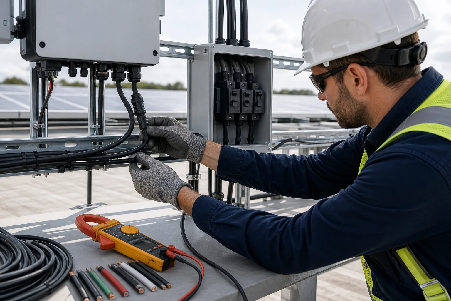
The installation matters near the SPD as well. Long connection leads add voltage during a fast transient; Schneider's SPD connection guidance explains why short connections help. Request the cabinet layout, connection lengths, bonding route and conductor requirements in the approved design. A suitably rated component mounted with a poor route can provide less effective protection at the equipment terminals.
A distributed roof may use coordinated protection at selected junction or distribution points. The designer should justify coverage of the farthest units and the paths between protected circuits; the cabinet enclosure, cable glands and service access must also fit the roof environment.
Read the inverter's surge report as a bounded test
“Surge tested” or an isolated kV number is insufficient procurement evidence. Request the exact model, hardware and firmware, test standard, tested ports, line-to-line and line-to-earth coupling, test levels, polarity, number of applications, operating conditions and performance criteria. Record any external devices used during the test.
IEC 61000-4-5 defines equipment surge-immunity tests under specified conditions and excludes direct lightning-current injection. Passing such a test does not establish protection against a direct strike or replace the site SPD design. The EMC documentation checklist helps connect report scope to the quoted configuration. The evidence should state whether the unit continued operating, recovered or required intervention, according to the applicable criterion.
Wi-Fi avoids a wired data path between some devices, but it does not remove the AC exposure. Review the gateway power supply and any actual Ethernet, meter or control wiring. Select signal protection for its electrical interface and data requirements rather than substituting an AC SPD.
Use a realistic review example and close the handover
Consider a proposed rooftop branch with 32 m from the main board to a roof distribution box and a further 18 m to the farthest inverter. These are illustrative distances, not a TMG customer case. The review should identify the existing board SPD, lightning protection arrangement, a justified roof-level protection location and coverage of the farthest equipment. The outcome depends on coordination and routing; the distances alone cannot determine the final BOM.
Before release, request the approved diagram, SPD schedule, coordination documentation, inverter surge report, cabinet drawings and inspection procedure. Allocate ownership: inverter supplier supplies product evidence; SPD supplier supplies application and coordination data; EPC designer selects the site arrangement; installer records the as-built routing and configuration.
At handover, record SPD part numbers, status, photos and replacement access, then set inspection intervals according to manufacturer instructions and site conditions. After a suspected surge event, preserve alarms, affected serials, SPD status and independent measurements using the RMA evidence checklist. Agree warranty and replacement responsibilities before installation.
Send the target market, selected microinverter model, AC network, branch layout, lightning protection details and proposed SPD schedule through TMG Contact. The quotation review can then identify product evidence and design items still needed for the project.
Sources & further reading
- https://webstore.iec.ch/en/publication/30774
- https://webstore.iec.ch/en/publication/32531
- https://webstore.iec.ch/en/publication/61166
- https://www.dehn-international.com/sites/default/files/media/files/wpo18-en.pdf
- https://www.electrical-installation.org/enwiki/Propagation_of_a_lightning_wave
- https://www.electrical-installation.org/enwiki/Connection_of_Surge_Protection_Device
Last reviewed October 7, 2026.