Microinverter AC Voltage Rise: A Pre-Quote Calculation Workflow
How EPC teams can screen cable routes, connection resistance and high-grid-voltage nuisance trips before confirming microinverter branch quantities.

TMG Technical Team
Applications Engineering
A microinverter may disconnect on high voltage even when it is operating correctly. Export current flowing through cable and connection impedance raises voltage at the inverter terminals. If the supply is already near the upper operating boundary, a modest additional rise can create nuisance trips.
This is why voltage rise deserves its own pre-quote calculation rather than being hidden inside an ampacity check.
Collect inputs from the complete AC route
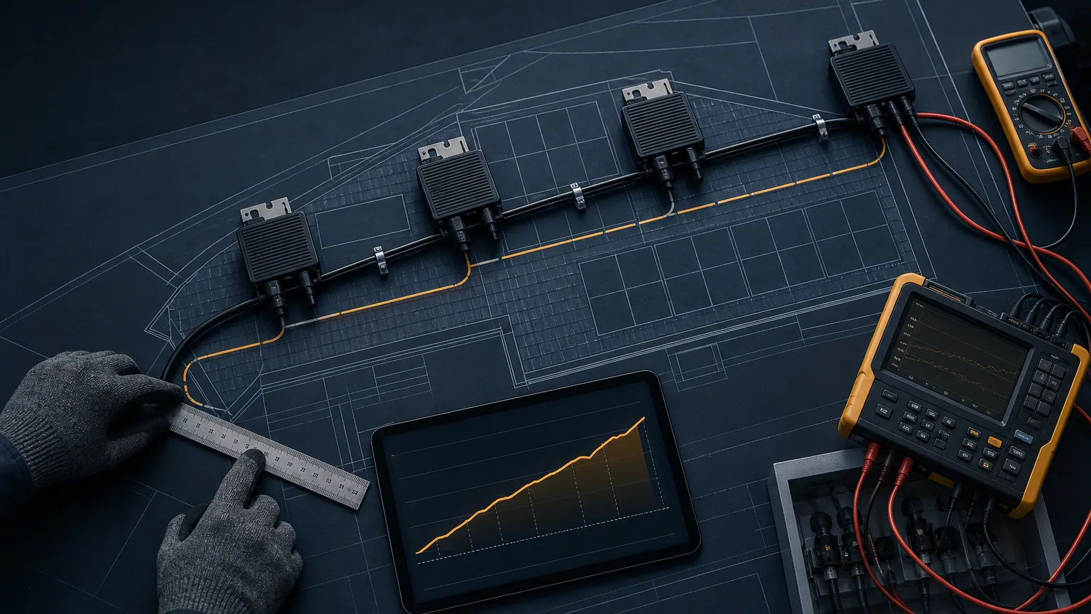
Start at the farthest generating unit and follow the path to the point of common coupling. Record conductor material, cross-section, route length, temperature, power factor, connector count, branch topology, protective devices and distribution-board links.
Measure or obtain representative supply voltage at the PCC. A single no-load reading is not enough for a site with known daytime voltage variation.
Model distributed current correctly
For a simple screening estimate, a single-phase section can be approached as:
Voltage rise ≈ export current × route impedance
The actual branch has generation injected at multiple points, so current is not constant along the entire cable. Divide the route into sections or use a design tool that represents the real topology. Include both outgoing and return conductors where applicable and the resistance of connections.
| Input | Weak assumption | Better record |
|---|---|---|
| Length | Straight-line roof dimension | Installed conductor route |
| Current | Total array current everywhere | Current by cable section |
| Voltage | Country nominal value | Site/PCC measurement profile |
| Connection | Zero resistance | Connector and terminal allowance |
| Temperature | Room-temperature conductor | Design operating temperature |
The AC branch circuit guide covers current limits and protective coordination; both checks should use the same cable schedule.
Compare against the approved grid profile
Do not “fix” trips by widening the inverter's voltage protection settings. The country or utility profile must remain controlled and supported by the required grid-code evidence. Confirm nominal voltage, trip behavior and reconnection rules using the grid voltage and phase guide.
The design margin should account for plausible PCC voltage plus calculated rise. The network operator or local standard may impose a project-specific voltage-rise limit; obtain that requirement rather than inventing a universal percentage.
Reduce rise at the design stage
Possible engineering responses include shorter routes, larger conductors, fewer units per branch, a different connection point, improved phase allocation or network-operator review. The responsible designer must assess cost, protection, connectors and installation constraints together.
Export limiting may reduce current, but it should not be used as an undocumented substitute for a compliant cable and grid-connection design.
Commission with paired measurements
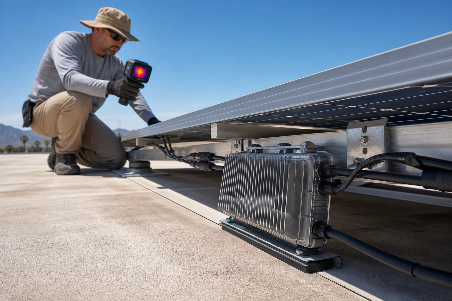
Record PCC voltage and inverter-terminal voltage at meaningful export, along with power, time and weather. Inspect connector seating, terminal torque under the approved procedure and any unexpectedly hot joints. If trips are intermittent, correlate event logs with voltage data rather than replacing hardware first.
The handover file should contain the route drawing, calculation version, assumptions, measured results and the approved country profile. DOE operational guidance also recommends investigating recurrent nuisance trips as a maintenance signal rather than repeatedly resetting equipment.
Send the branch layout, cable schedule, PCC voltage data and unit count through TMG Contact. A pre-quote review can identify whether the proposed architecture has enough voltage margin before equipment is shipped.
Sources & further reading
- https://www.energynetworks.com.au/projects/national-grid-connection-guidelines/
- https://www.energy.gov/cmei/femp/life-cycle-photovoltaic-systems-operate-and-maintain-existing-photovoltaic-system
Last reviewed August 14, 2024.