Microinverter Thermal Derating in Hot Climates: A Design Review
Estimate the local thermal environment, preserve natural convection and obtain model-specific output curves before promising continuous power.

TMG Technical Team
Applications Engineering
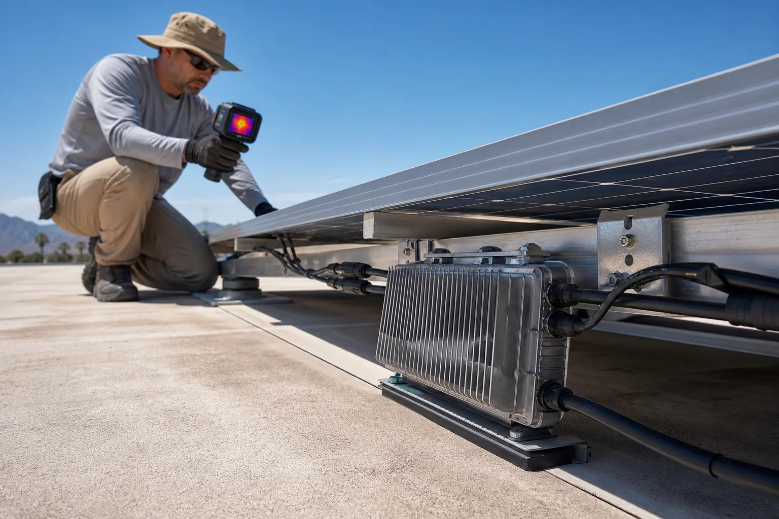
Weather-station air temperature is not necessarily the temperature around a microinverter behind a sun-heated module. Restricted airflow, roof temperature, irradiance and neighboring equipment can create a harsher local condition.
An operating-temperature range shows where equipment is designed to function. It does not prove that rated AC output is available without derating at every point.
Define the mounting microclimate
Collect design ambient range, solar exposure, roof or façade material, distance behind the module, ventilation, orientation, nearby heat sources and expected dust. Include recesses or decorative covers that trap hot air.
IEC TS 63126 illustrates why PV deployment temperature needs explicit qualification: module temperatures can exceed baseline assumptions in high-temperature mounting conditions. The inverter is a separate product, but experiences the same microclimate.
Request model-specific derating data
Ask for the relationship between output and the relevant temperature condition, including dependence on input or grid voltage. Clarify where temperature is measured and whether the curve is test data or installation guidance.
Do not transfer a curve between power variants because housings look alike. Thermal loading and firmware limits can differ.
Preserve the cooling path
The APLV and APHV platforms use fanless natural cooling. Follow mounting instructions, keep clearances and avoid an unapproved weather box or insulation around the housing.
| Design question | Evidence needed |
|---|---|
| Peak local temperature | Site assumption and mounting section |
| Continuous output | Model-specific curve or statement |
| Required clearance | Installation manual |
| Enclosure orientation | Approved drawing |
| Neighbor spacing | Array layout |
| Dust risk | Maintenance plan |
Ingress protection does not replace thermal design. Review What IP67 Does and Does Not Prove.
Model and commission the consequence
If output falls during hot, high-irradiance hours, clipping can increase. Model a sensitivity using the expected temperature profile and keep this loss separate.
During a hot operating period, record output, local temperature at defined locations, grid voltage and time. Never place sensors where they block cooling or create electrical risk. One observation cannot validate annual behavior, but can reveal a mounting condition outside the assumption.
Send the layout, mounting section, climate data and required output through TMG Contact. The review should return installation conditions and any output limitation that belongs in the proposal.