Microinverter RCD and RCMU Coordination: An EPC Evidence Review
A safe workflow for reviewing residual-current behavior, internal monitoring, external RCD selection and nuisance-trip risk without guessing device type.

TMG Technical Team
Applications Engineering
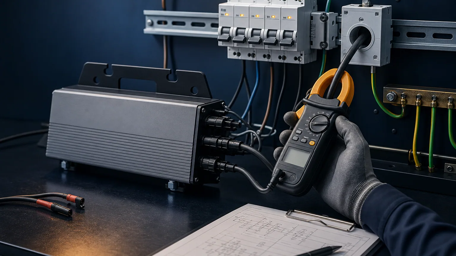
Residual-current protection for a PV circuit cannot be selected from inverter wattage alone. The EPC must coordinate the inverter's topology and internal residual-current monitoring with the installation standard, earthing arrangement, upstream protection and local authority requirements.
This article is an evidence checklist, not a substitute for design by a qualified electrical professional.
Keep three functions separate
An external residual current device can provide protection required by the installation. An internal residual current monitoring unit can detect specified leakage behavior and cause the inverter to disconnect. Insulation monitoring is another function again. One label does not prove equivalence among them.
IEC 62109-2 addresses particular safety requirements for PV inverters and is used with IEC 62109-1. IEC 60364-7-712 covers the application of low-voltage electrical installations for PV systems. The adopted edition and national deviations must be confirmed for the project location.
Request a model-specific residual-current statement
Ask the manufacturer to state:
- Whether the inverter provides galvanic isolation
- Whether DC residual current can be injected onto the AC side
- Which internal residual-current monitoring functions are present
- Detection thresholds and disconnect behavior, where discloseable
- Conditions or limitations for any external RCD recommendation
- Applicable safety report and exact model scope
- Whether multiple units on one RCD require an accumulation assessment
Do not accept “RCD built in” as a complete answer. The file should distinguish monitoring from protective switching and identify what still has to be supplied by the installer.
Calculate cumulative leakage before final selection
Filters, cables and connected electronics can create normal operational leakage. When many microinverters share one upstream device, those currents can accumulate. A protective device chosen too close to normal leakage may trip intermittently; one chosen incorrectly can fail to meet the applicable safety design.
| Design input | Project record |
|---|---|
| Inverter quantity and topology | Exact model schedule |
| Manufacturer leakage information | Controlled technical statement |
| Cable type and route | AC cable schedule |
| Earthing arrangement | Single-line and site data |
| Upstream protective devices | Coordination schedule |
| Local code/AHJ requirements | Approved design basis |
The AC branch sizing checklist should be completed at the same time because branch layout, conductor routing and protective devices are linked.
Diagnose nuisance trips with evidence
Do not respond to repeated tripping by installing a different device without investigation. Record time, weather, operating power, affected branch, insulation readings and whether the event follows rain, startup or communications activity. Inspect water ingress, damaged cables, connector contamination and neutral/earth faults.
Compare event data from the inverter with the protective device indication. Monitoring loss alone is not evidence of an electrical trip. If insulation testing is required, follow the manufacturer's disconnection procedure to avoid damaging electronics.
Put the decision in the commissioning file
The final record should identify the external device, poles, rating, sensitivity/type as selected by the responsible designer, protected circuits, test result, trip investigation method and supporting manufacturer statement. Label shared circuits clearly.
Also verify anti-islanding and grid-disconnection evidence separately; see the anti-islanding guide. These functions may all disconnect generation, but they address different hazards.
Send the single-line diagram, earthing arrangement, inverter quantity and local requirements through TMG Contact. TMG can supply product evidence for configuration review; the qualified EPC and authority having jurisdiction remain responsible for final protective-device selection.
Sources & further reading
Last reviewed September 15, 2026.