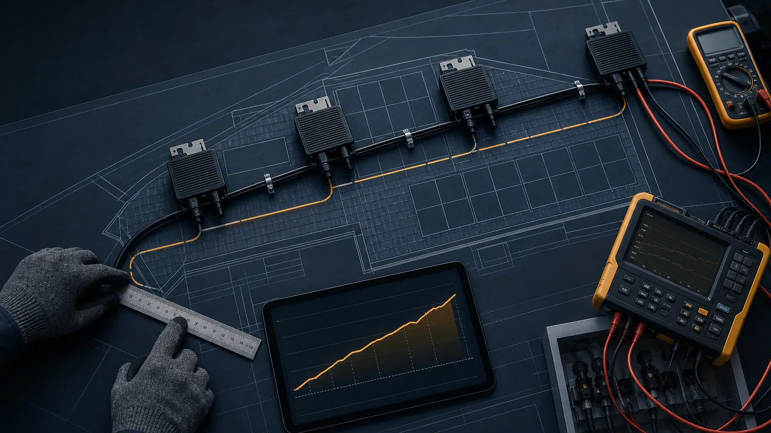
Battery Matching for a Low-Voltage Hybrid Microinverter Project
A B2B interface checklist for battery voltage, current, BMS limits, protection, charging schedules and responsibility boundaries.

TMG Technical Team
Applications Engineering
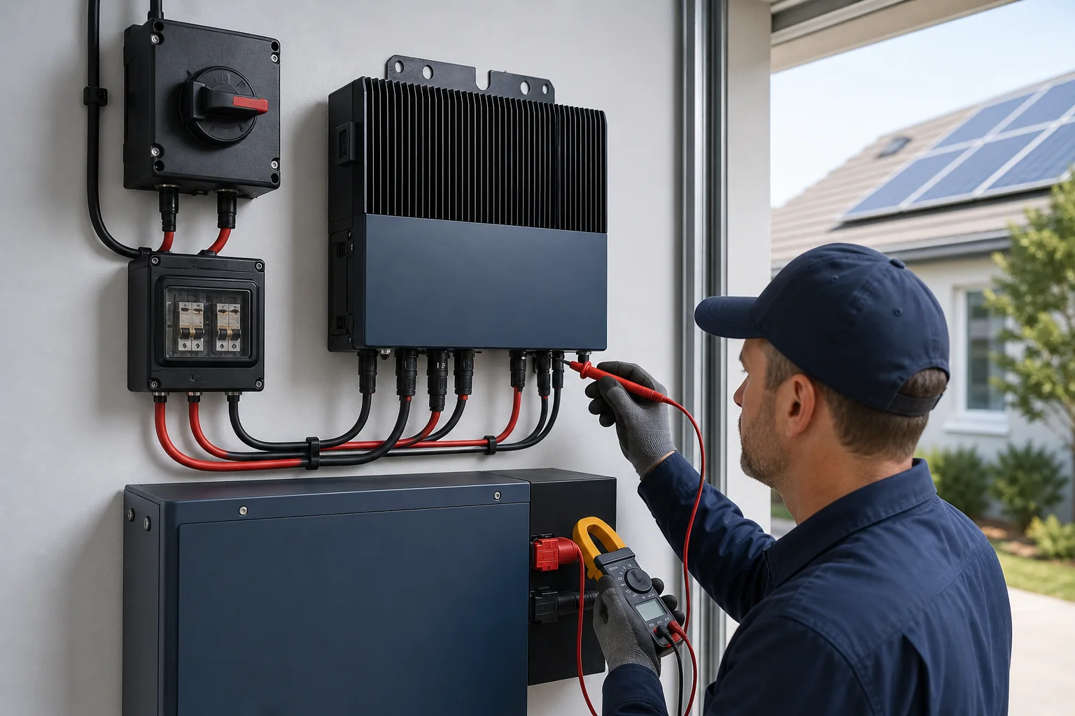
A battery label that says 24 V or 48 V does not establish compatibility with a hybrid microinverter. Procurement teams must compare the complete operating voltage window, allowable charge and discharge current, BMS behavior, protection and intended operating mode.
The APLV Series supports low-voltage hybrid functions including PV battery charging and scheduled AC reverse charging in compatible configurations. Final battery and system design still require project review.
Build a two-sided interface table
Obtain these battery values from a controlled manufacturer document:
- Chemistry and series/parallel configuration
- Nominal, minimum and maximum operating voltage
- Recommended and absolute charge current
- Permitted discharge current and time limits
- BMS cutoff and restart behavior
- Low- and high-temperature charge restrictions
- Required pre-charge, contactor or wake-up process
- Communication interface, if required
- Protective device and cable recommendations
Compare them with the exact inverter model, not only the family range.
Check voltage across all states
The battery's maximum charged voltage must remain within the supported interface, while low state-of-charge voltage must still support the intended function or a defined shutdown. Include manufacturing tolerance, temperature behavior and voltage drop under load.
Do not bypass a BMS cutoff or alter protection thresholds to make an incompatible combination operate.
Calculate current and conductors
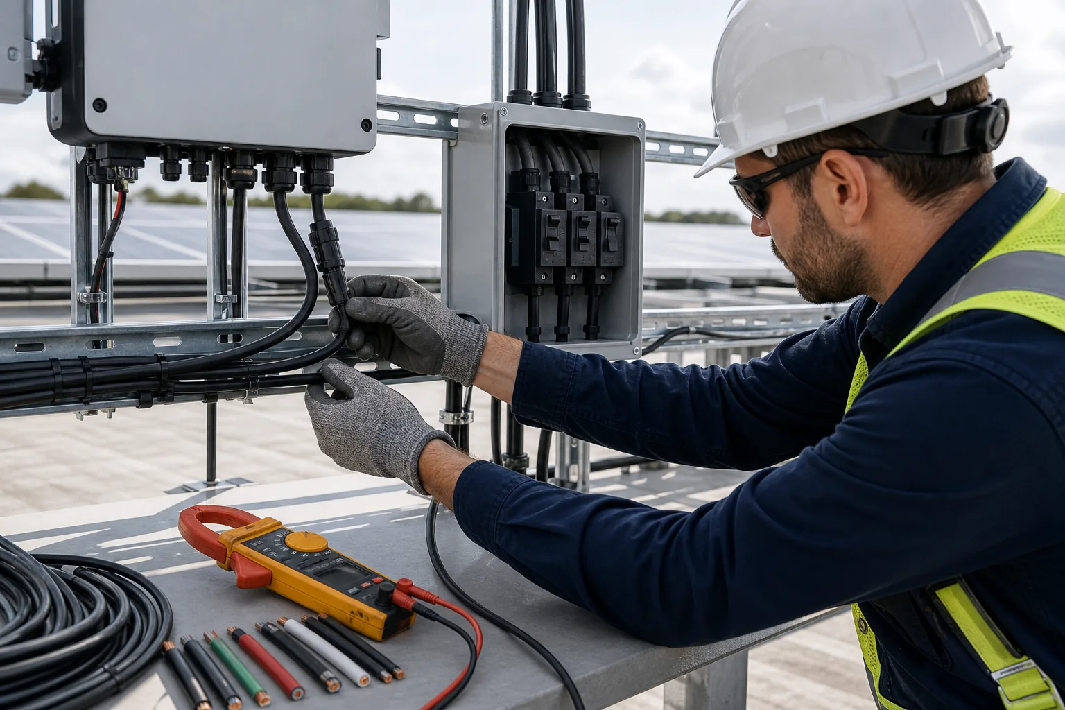
At low DC voltage, substantial power requires high current. The responsible designer must size conductors, connectors, isolation and overcurrent protection for the permitted current, route, temperature and installation method. Long or undersized battery leads create voltage drop and heat even when average power looks acceptable.
Use the connector and cable order checklist to lock the finished lead and termination parts.
Define operating modes before quotation
| Mode | Questions to close |
|---|---|
| PV charging | Charge limit, temperature rule, full-charge behavior |
| AC reverse charging | Schedule, power limit, tariff objective |
| Off-grid supply | Load profile, surge, reserve state of charge |
| Grid tied | Export limit and local permission |
| Standby | Self-consumption and restart logic |
State who controls each limit: inverter, BMS, external controller or operator. If communication is not used, document how hardwired voltage and current limits coordinate.
Assign safety and warranty responsibility
The inverter supplier should approve the inverter interface; the battery supplier should approve the battery application; the system integrator owns the combined design and local installation compliance. Put warranty boundaries, firmware versions, commissioning settings and fault-escalation responsibilities in the project file.
The APLV versus APHV guide helps confirm whether hybrid operation is the right architecture. Then send the battery datasheet, BMS manual, load profile, PV allocation and target market through TMG Contact for a conditional configuration review.
Sources & further reading
Last reviewed September 9, 2025.