PV Connector and Cable Checks Before a Microinverter Purchase Order
A distributor-level BOM review for connector families, conductor ratings, sealing parts and AC branch accessories before an order is released.

TMG Technical Team
Applications Engineering
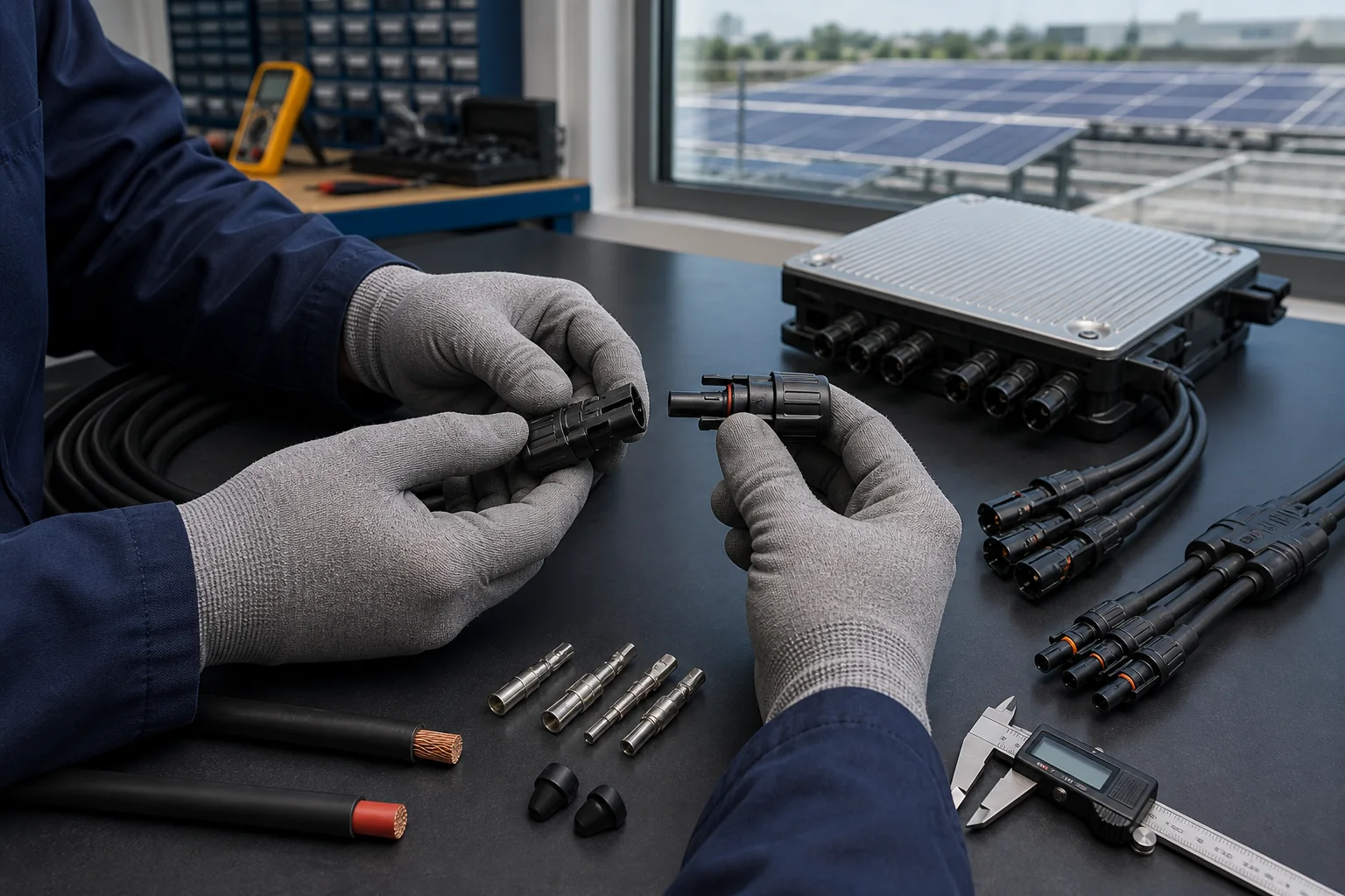
A microinverter purchase order can name the correct inverter and still produce an unusable kit. Connector families, cable cross-sections, branch accessories and sealing parts must be frozen with the electrical design, not added after production.
This guide is for distributors and EPC procurement teams converting an approved configuration into a complete bill of materials. It complements the module compatibility checklist, which focuses on the inverter input rather than the field wiring package.
Do not approve connectors by appearance
PV connectors that look similar are not necessarily qualified to mate. Contact geometry, plating, tolerances, sealing and locking features belong to a connector system. IEC 62852 covers safety requirements and tests for DC connectors used in photovoltaic systems, but a component's compliance does not prove that two different manufacturers' halves are an approved pair.
The purchasing file should identify the manufacturer, exact family, contact size, housing gender, conductor range and approved mating combination. Avoid descriptions such as “MC4 compatible” unless the responsible manufacturer provides a precise compatibility statement for the parts supplied.
Freeze the DC cable specification
For every PV input lead, record:
- Conductor material and cross-sectional area
- Insulation type, voltage and temperature rating
- Outdoor, UV and environmental suitability
- Minimum bend radius and permitted installation method
- Connector contact matched to that conductor size
- Finished lead length and polarity
- Factory crimp and pull-test controls
Cable sizing is not a watts-only calculation. The designer must consider current, installation temperature, bundling, voltage drop, local rules and the rating of every termination in the path.
Treat the AC branch as a designed assembly
Microinverter AC outputs are commonly combined along a branch. The BOM therefore needs more than “AC cable.” Confirm the conductor count, neutral and protective-earth arrangement, connector pinout, branch current limit, maximum unit count, end cap, disconnect interface and any transition cable.
| Purchase-order field | Why it matters | Evidence to request |
|---|---|---|
| AC connector family | Prevents mismated field parts | Drawing and part number |
| Conductor cross-section | Supports current and voltage-drop review | Cable specification |
| Maximum units per branch | Sets the design boundary | Model manual |
| End-of-branch sealing | Maintains enclosure protection | Assembly instruction |
| Earthing path | Supports protective design | Wiring diagram |
| Cable length | Affects installation and voltage drop | Approved layout |
The APHV Series lists a maximum branch quantity for its 230 V configuration. That product value is an upper boundary, not automatic approval for every cable length, protective device or local installation method.
Inspect samples as finished assemblies
During sample approval, check polarity, pin position, locking engagement, crimp quality, strain relief, seal placement, cable marking and dimensional fit. Use the specified mating parts and the installation tools intended for production. A loose bench connection does not reproduce outdoor mechanical and environmental stress.
Record the inspected sample with photographs, part numbers and revision codes. If an accessory supplier changes, repeat the relevant review instead of assuming equivalence.
A practical order-release gate
Do not release a production order until the controlled BOM includes:
- Inverter model and firmware or country-profile requirement
- DC leads and exact connector system
- AC branch cable and all branch accessories
- End caps and unused-port sealing parts
- Protective and isolation interfaces within the agreed supply scope
- Labels, diagrams and installation instructions
- Spare-parts quantity and replacement-part policy
Send the proposed wiring diagram, module datasheet, unit count and destination market through TMG Contact. The review should end with a signed configuration and BOM, not a collection of informal chat messages.
Sources & further reading
Last reviewed October 29, 2024.