Off-Grid Microinverter Load Sizing: Continuous Power Is Only the Start
A project checklist for running watts, startup surge, power factor, battery limits, load priority and recovery behavior.

TMG Technical Team
Applications Engineering
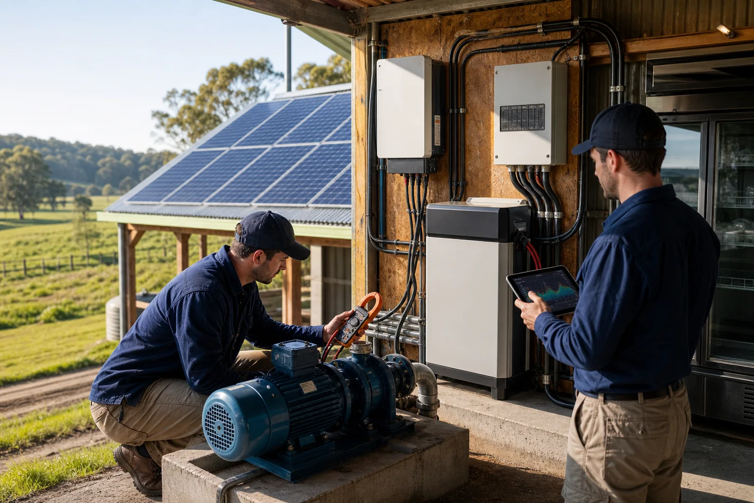
An off-grid output should not be selected by adding appliance nameplate watts alone. Motors, compressors, pumps, transformers and electronic power supplies can demand startup current or behave poorly with a weak source. Battery and PV availability also determine how long the load can operate.
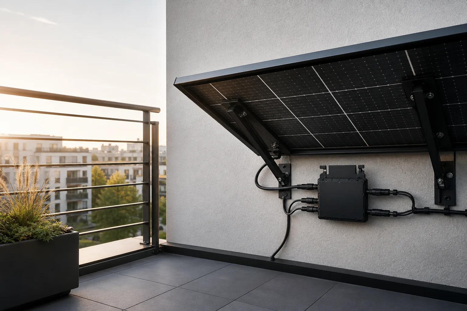
The APLV Series includes an independent off-grid output in compatible designs. Treat it as a controlled microgrid interface, not as an unlimited substitute for the public grid.
Build a time-based load schedule
List every intended load with running power, startup or inrush information, power factor where relevant, duty cycle, operating hours and whether loads can start together. Use manufacturer data or measured profiles from appropriate instruments; do not invent a universal surge multiplier.
Separate critical loads from discretionary loads. This allows load shedding before a low battery causes the entire output to stop.
Check four capacity limits
- Continuous inverter output: combined steady load under the expected temperature.
- Short-duration overload or surge: magnitude and duration compared with documented capability.
- Battery discharge: BMS current, voltage sag and state of charge.
- Available energy: usable battery energy after limits and losses, plus expected PV contribution.
A system can pass the watts check and still fail when battery voltage drops during a motor start.
Examine load quality
Ask whether the load is inductive, capacitive, rectifier-based or sensitive to interruption. Record required voltage and frequency tolerance. Some equipment has a low running wattage but high inrush; other devices produce high harmonic current or reset during a short transfer.
| Load | Data to obtain | Design response |
|---|---|---|
| Refrigerator/compressor | Locked-rotor or startup profile | Verify surge and restart delay |
| Pump | Motor type and head condition | Review start method |
| LED driver | Inrush and quantity | Avoid simultaneous energization |
| Router/controller | Ride-through requirement | Consider dedicated reserve |
| Heater | Continuous watts and duty | Energy, not surge, dominates |
Define recovery behavior
Document what happens after overload, low battery, overtemperature and a communications failure. Confirm whether restart is automatic or manual, whether loads reconnect in stages and how the operator sees the fault.
Coordinate with the battery and PV design
Use the battery matching checklist for voltage, BMS and cable limits. Then model a low-solar case rather than assuming PV output equals module nameplate. State the reserve state of charge and acceptable runtime.
The Micro Generation System can support lightweight deployment scenarios, but final electrical specifications remain project configured. Send the load schedule, startup data, battery documents, PV design and required autonomy through TMG Contact. A useful proposal identifies excluded loads and operating rules as clearly as supported loads.
Sources & further reading
- https://www.energy.gov/cmei/systems/solar-integration-inverters-and-grid-services-basics
- https://webstore.iec.ch/en/publication/6470
Last reviewed September 25, 2025.